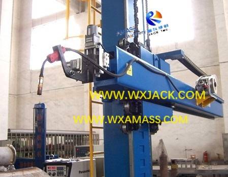
1. Outline on Fixed Base Motor Revolve Medium duty Welding Manipulator:
The three key words describing the Weld Manipulator of this product section are:
1) Medium loading capacity at front end of boom;
2) Stationary mechanical base bed;
3) Electric motor drive of the upright column rotation;
In all, this product is a Medium duty Welding Column and Boom with automatic column revolving function.
2. Application and Applicable Workpieces of Medium duty Welding Column and Boom:
1) Extension of Working Stroke: With horizontal boom moving strokes enlarged from 2000 mm in light duty models, to 4000 mm strokes in both X axis horizontal direction and Y axis vertical direction, workpieces applicable for this series machine tool are also turned from small diameter Pipe/ Tube, to larger diameters Tank / Cylinder, and other big scale Vessels;
2) This is the reason why the Welding manipulator has the other name of Tank Welding Machine;
3) Welding Center: Under majority conditions, the medium duty models work together with Self Adjusting or Bolt Adjusting Welding Rotator, for completing internal and external longitudinal and circumferential seam welding.
3. Upright Column Revolve in Medium duty Motor Drive Stationary Welding Column and Boom:
1) Working Way: In this welding equipment, upright column revolve is driven with motor drive. The motor is of braking type, for conveniently stopping at any angular position reliably during running;
2) Transmission chain for the upright column revolve is: Braking motor –- Gear –- Slewing support unit – Column, with limit switches for hard security;
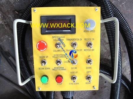
3) Operation is by means of the pushbutton on operating panel: (Fig.1)

4. Workpiece Loading and Unloading in Welding Column and Boom for Tank Welding:
1) For stationary models, the max. reach scope of its horizontal boom is the full circle surrounding it;
2) So, large diameter and relative heavy weight tanks/ cylinders should be sent to working station beneath horizontal boom of this Tank Welding Machine, utilizing auxiliary unit such as travel crane and sling.
5. Welding Mode in Medium duty Welding Manipulator Tank Welding Machine:
1) SAW: Majority conditions are adopted with large current submerged arc welding, making the equipment a set of Automatic Column and Boom with SAW;
2) Gas Shielded Welding: When the workpieces are made of materials such as stainless steel and or Al, CO2 GMAW should be selected;
3) Built-Up Welding: Sometimes for welding anti-septic layer or anti-abrasion layer at external surface of workpieces, the Welding Manipulator should be equipped with strip surfacing power supply, making its welding mode as strip cladding. More detailed introduction is in product section of “LHZ Model Accurate and Fast Welding Manipulator with Strip Cladding”.
6. The Role of Cross Slides Saddle for Boom Traveling in Welding Manipulator:
1) This working element has the other name of cross slide. It is the pivot in working period of the equipment;
2) The below picture shows how does the saddle looks when fit onto the medium duty models:
Cross slides in assembled Welding Column and Boom: (Fig.2)

3) Horizontal Sliding: As can be seen from the above picture, horizontal boom is installed by means of the upper and lower two arrays of eccentric rollers at the front side of the saddle. Or, in other words, top and bottom surfaces of the horizontal boom is snapped between the 4 pieces of eccentric rollers. In this way, during operation, horizontal movement of the boom can be guided in smooth, precise, and reliable way;
4) Vertical Sliding: The same is true with elevating movement mechanism of the horizontal boom: the external surfaces of upright column guideway are snapped between the left and right 2 arrays of eccentric rollers at the rear side of the saddle;
5) To have more precise management on the horizontal boom movement in the period of complicated welding, these rollers are the kind of eccentric types, which means inching control available for precision manipulation, making the Tank Welding Machine a genuine sense of accurate welding operation.
7. Technical Parameters of Fixed Base Motor Revolve Medium duty Welding Manipulator:
Fixed Base Motor Revolve Welding Column and Boom |
Model | LHZ 3×3 | LHZ 3×4 | LHZ 4×4 | LHZ 4×5 |
Boom Vertical Sliding Stroke (mm) | 3000 | 3000 | 4000 | 4000 |
Boom Horizontal Sliding Stroke (mm) | 3000 | 4000 | 4000 | 5000 |
Boom Vertical Sliding Speed (mm/min) | 1000 |
Boom Horizontal Sliding Speed (mm/min) | 120 ~ 1200 |
Min. Distance between Horizontal Boom Bottom Surface and Traveling Rail Top Surface (mm) | 740 ~ 1180 |
Max. Loading at Front End of Boom (kg) | 80 ~ 120 |
Column Revolve Way | Motor Drive, 0.17rpm |
Trolley Travel Speed (mm/min.) | N/A |
Inner Span of Trolley Rail (mm) | N/A |


