1. The Working Specialty of Light duty Electric Revolve Moving Welding Manipulator:
1) Powerful Capabilities: This is the most “Capable” type of light duty Weld Manipulator. It has motor drive moving trolley, for moving along the entire length of rails for workpiece pipes during work; With function of motor drive automatic column revolve, for reaching on more working zone at workshop;
2) Strong Points: The two functions extend activity scope of this Convenient Welding Manipulator greatly, flexible for coping with wide variety and changing requirement at customer site. It is also the largest share of LHZ series welding equipment product in practical application.
2. Characteristic and Usage of Main Working Unit in Moving Welding Column and Boom:
Below is draft on constructure and formation of a typical moving type model: (Fig.1)
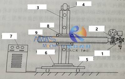
Below is brief introduction on main units of the welding machine tool based on and in the sequence of marked figures in the above:
1) Welding Head in the High Efficiency Welding Manipulator:
Welding head being installed at front end of horizontal boom: (Fig.2)
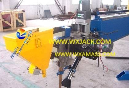
As shown in the above photo, welding head mainly composes of:
a) Welding torch and wire feeder;
b) Welding torch and wire feeder are equipped together with welding power source;
c) Different types of welding modes can be adopted in this Efficient Welding Column and Boom. For example, with the selection of corresponding welding heads, it can be a set of SAW, or GMAW, or TIG, or Strip Cladding, etc.;
d) Welding Modes: Working together with other welding equipment such as Welding Positioner, the Welding Manipulator can be set up as a dedicated use Pipe Flange MIG Welding Center;
e) Other Operations besides Welding: Besides welding, this Convenient Welding Column and Boom can also fulfil operations other than welding, such as Carbon Arc Gouging, Polishing, Painting, etc., which need the installation of corresponding function units;
2) Welding Head Function Units in the Automatic Weld Manipulator:
Welding function units being equipped: (Fig.3)
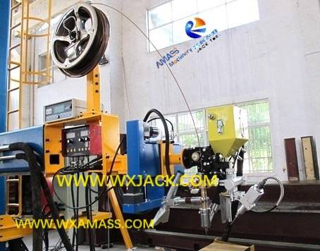
As shown in the above photo, the major function elements include:
a) Control console of welding power source;
b) Control console of wire feeder;
c) Mechanism for adjusting and controlling welding torch up and down, left and right, for aiming at welding seam perfectly all along, during welding operation in the Moving Welding Manipulator;
d) Optional unit of welding seam tracing element, as well as video monitor, are also installed at welding head;
3) Upright Column in the Moving Welding Column and Boom:
a) Role: This is “Basic trunk” in a set of Welding Manipulator, which supports vertical and horizontal movement of horizontal boom;
b) Structure: Upright column is steel structure member, which has cross section of rectangular shape, being processed with steel plate bending and welding;
4) Horizontal Boom Elevating Motor in Moving Welding Column and Boom:
a) Position: Generally speaking, this motor is fit at top of the usually column. So, it is apex in a set of Weld Manipulator;
b) Type: For safety purpose, this is braking type motor, which is transmitted with worm gear reducer;
5) Mechanical Base or Moving Trolley in the Moving Welding Manipulator:
a) In moving type models, it is in the form of motor drive moving trolley;
b) In stationary type Weld Manipulator, it is in the form of cross base for light duty welding equipment, and box structure bed for medium and heavy duty Welding Column and Boom;
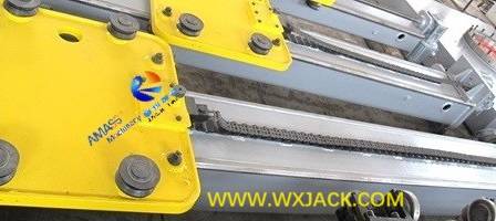
c) For moving type Welding Column and Boom, inside the moving trolley is installed with motor reducer. There are 4 pieces of wheels fit at bottom of the trolley; Welding power source usually is put on the trolley of the moving welding machinery;
6) Slewing Support in the Moving Welding Column and Boom: (Fig.4)
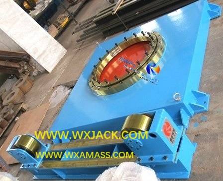
Shown in the above illustration, this round shape finely machined gear is outsourced part of the automatic welding machine tool, which is fit inside the square shape bed, for leading and guiding revolving of the upright column;
7) Welding Power Source in the Moving Welding Manipulator:
a) Location of the welding power source equipped in the draft is not the only choice;
b) As mentioned in item 5, for a set of high efficiency Moving Welding Manipulator, usually the welding power supply is put on the traveling trolley;
c) For fixed base type models, welding power supply is put on the workshop floor;
8) Cross Slide (or, Saddle): (Fig.5)
a) This can be viewed as the joint of the Automatic Welding Column and Boom;
b) As can be seen from the above small photo, the cross slides (Saddle) guides both vertical and horizontal movement of boom during working period, this is the name “cross slide” derives;
c) Based on shape of this unit, cross slide is also named as “Saddle”;
d) Cross slides (Saddle) in light, medium and heavy duty models has slightly different appearance, but working principle is all the same;
9) Horizontal Boom in the Moving Welding Manipulator:
a) It is “Arm” or “Working hand” in any set of the Column and Boom welding equipment;
b) Operating unit (welding group) is fit at its front end;
c) Same as upright column, horizontal boom is steel structure member with square shape cross section, which is processed in Press Brake first and then Welding Machine.
3. Technical Parameters of LHZ Light duty Electric Revolve Moving Welding Manipulator:
LHZ Light duty Electric Revolve Moving Welding Column and Boom |
Model | LHZ 2×2 | LHZ 2.5×2.5 | LHZ 2.5×3 |
Boom Vertical Moving Stroke (mm) | 2000 | 2500 | 2500 |
Boom Horizontal Moving Stroke (mm) | 2000 | 2500 | 3000 |
Boom Vertical Moving Speed (mm/min.) | 1000 |
Boom Horizontal Moving Speed (mm/min.) | 120 ~ 1200 |
Min. Distance between Boom Bottom Surface and Rail Top Surface (mm) | 740 |
Max. Loading at Front End of Boom (kg) | 80 |
Column Revolve Way | Motor drive, 0.17rpm |
Trolley Moving Speed (mm/min.) | 1700 |
Internal Span of Trolley Rails (mm) | 1000 |


