1. Outline on Usage of HBS150 Model Double Column Elevating type Welding Positioner:
1) Working Feature of HBS150 Model Head and Tail Elevating type Welding Positioner:
Workpieces fixed onto this HBS150 model Servo Drive Welding Positioner can be adjusted to the optimum position for fabrication, by means of elevating and 0°~360° infinite revolve of its Welding Turning Table and workpiece;
2) Applicable Workpiece of HBS150 Model Elevating and Revolving Servo Drive Welding Positioner:
This 15 Ton loading capacity Head and Tail Welding Positioner is suitable for fabricating on structure member workpieces with long length and heavy weight, which are common seen in industries of Vehicle and Engineering Machinery;
3) Welding Turning Table Revolve:
To make sure reliable revolve of long and heavy workpiece in this welding equipment, each of the upright columns (Headstock and tailstock) has motor reducer for driving workpiece into revolve;
4) Layout of the Erected Two Columns in HBS150 Model Head and Tail Elevating and Revolving Welding Positioner:
a) At customer site, one piece of the upright column is fixed into workshop floor --- Headstock;
b) The other column can be moved along rail under motor drive, and locked into position manually by means of anchor bolts --- Tailstock;
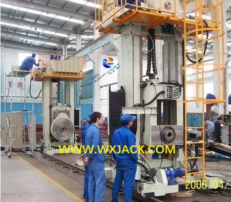
Appearance of Wuxi JACK HBS150 model in workshop: (Fig.1)
2. Structure of HBS150 Model Head and Tail Elevating and Revolving Servo Drive Welding Positioner:
1) Main units of Double Column Elevating and Revolving Welding Positioner:
a) Stationary upright column (Headstock);
b) Motor drive moving upright column (Tailstock);
c) Workpiece elevating mechanism;
d) Workpiece revolve mechanism;
e) Electric control system;
2) With the structure of double columns, this Head and Tail Servo Drive Welding Positioner has ideal stress condition. The entire set of the Elevating type welding positioning equipment runs safely, reliably and consistently;
3) The Fixed Stationary Upright Column (Headstock) in HBS150 Head and Tail Elevating and Revolving Welding Positioner:
a) The fixed column (Headstock) is secured firmly into workshop floor by means of anchor bolts;
b) Its vertical middle section is installed with workpiece elevating and revolving mechanisms, which are guided along the upright column with the structure of 4 sides guiding rollers, shown as below:
Workpiece elevating and revolving mechanisms and its Welding Turning Table: (Fig.2)
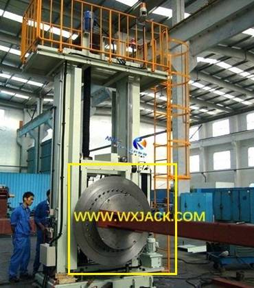
c) The top section is platform which is installed with motor reducer for driving elevating mechanism. Please check the above photo also;
d) Lateral side is installed with climbing ladder;
4) The Motorized Moving Upright Column (Tailstock) in HBS150 Head and Tail Elevating type Welding Positioner:
a) There are traveling wheels and motor reducer installed at bottom of the column, driving the integral set of the upright column into moving along the rail, to be adaptable for fixation of workpieces in varying lengths;
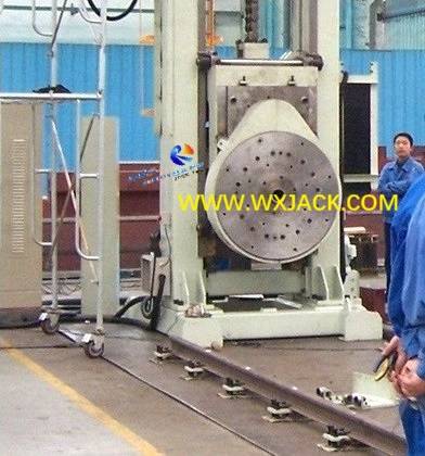
b) Traveling rails are of C cross section structure, (Please check the photo as below), which means the wheels move along lower section of the C rail, and its top section is installed with fender plates which prevent the columns from dumping down:
C structure rails in HBS150 Double Column Elevating and Revolving Welding Positioner: (Fig.3)
5) Elevating Mechanisms at Headstock and Tailstock of Servo Drive Welding Positioner:
a) The 2 groups of elevating mechanisms at both sets of the columns are driven with high power (4kW x 2) servo motors, ensuring perfect in phase elevation at both sides of the workpiece;
Both sides in phase revolve of workpiece in HBS150 Head and Tail Welding Positioner: (Fig.4)
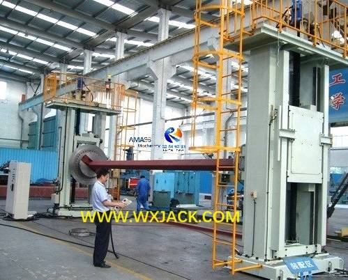
b) Besides, servo drive can guarantee on workpiece stoppage at the same height level perfectly of the 2 sets of elevating mechanisms;
c) The 2 groups of elevating mechanisms at both sets of the columns are transmitted with chain and sprocket. The worm gear reducer has self-lock function, avoiding the hidden risk of accidental falling down of elevating mechanism, Welding Turning Table and workpiece;
6) Revolve Transmission in HBS150 Elevating and Revolving Servo Drive Welding Positioner:
a) Chain of workpiece revolve transmission is: Revolve brake motor→ Double stage reduction gear→ Small gear→ Cross roll bearing→ Welding Turning Table revolve;
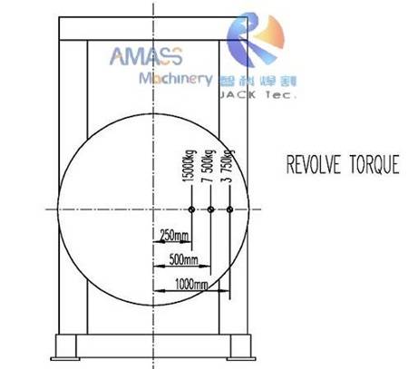
b) The self-lock function is acquired from worm gear reducer. That is, when the Welding Turning Table is in revolve, and loading eccentricity is within stipulated range, the Welding Turning Table will not revolve on its own. Loading eccentricity is restricted with loading capacity (15 Ton) of the Servo Drive Welding Positioner;
c) The relationship between eccentricity and revolving capacity for this HBS150 Head and Tail Elevating type Welding Positioner is shown as below: (Fig.5)
3. Technical Parameters of HBS150 Model Elevating and Revolving Servo Drive Welding Positioner:
No. | Model | HBS150 Head and Tail Elevating and Revolving Welding Positioner |
1 | Loading Capacity | 15,000 kg |
2 | Welding Turning Table Revolve Speed Range | 0.08-0.8 rpm |
3 | Power of the Revolve Motor | 5.5kW *2 |
4 | Diameter of the Welding Turning Table | Φ1800 mm |
5 | Max. Eccentricity for Revolve | 250 mm (See as the design sketch Fig 1. below) |
6 | Welding Turning Table Revolve Range | n* 360° (Infinite revolve) |
7 | Revolve Speed Adjustment | Revolve speed is VFD. (Ordinary brake motor) 14
|
8 | Workpiece Lifting Stroke | 2000 mm |
9 | Workpiece Lifting Speed | 800 mm/min, constant speed. (Brake motor) |
10 | Workpiece Lifting Motor | Servo motor drive for two side lift at same position |
11 | Power of the Workpiece Lifting Servo Motor | 4kW * 2 |
12 | Control Box | One set |
13 | Power Specification | 380V, 50Hz, 3 Phase |


