1. Application of YTJ-50 Hydraulic H Beam Straightening Machine:
1) This set of YTJ-50 model in the first photo was taken at a busy working steel structure facility. You can find from the photo that there are finished product of many welding H Beam laid on the workshop floor. There are other H Beam Production Machine in the far distance: A set of H Beam End Face Milling Machine;
2) YTJ-50 is the middle model of YTJ series hydraulic drive models, and also the often used type;
3) YTJ-50 has the same straightening principle as YTJ-40 Hydraulic I Beam Flange Straightening Machine: (Fig.1)
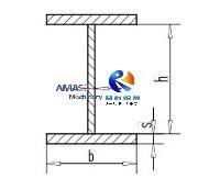
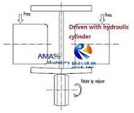
4) Note: YTJ-40 and YTJ-50 has similar straightening principle as HYJ series mechanical structure machine. The difference lies in driving power source of the top straightening rollers: The YTJ-40 and YTJ-50 models are driven with hydraulic pump station, while the HYJ series H Beam Straightening Machine is driven with mechanical motor reducer.
2. Main units of the YTJ-50 Hydraulic H Beam Straightening Equipment:
1) Main Frame and Base: (Fig.2)
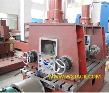
This is the mounting bed and working area of the machine. All the important working elements are installed here;
2) Front side and rear side conveyor of YTJ series: (Fig.3)
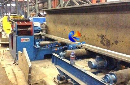
This units are for loading in flange deformed welding H Beam into the machine, and loading the straightened welding H Beam out of the machine;
3) Straightening Roller unit of YTJ series: (Fig.4)
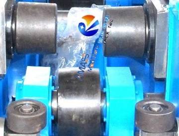
This includes two pieces of top rollers and one piece of bottom roller. These elements are the central execution mechanism of the YTJ series;
4) Hydraulic station of machine: (Fig.5)
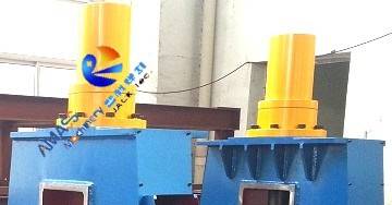
This system includes hydraulic oil cylinders for pressing top straightening rollers downward. It is the energy source of the H Beam Straightening Equipment;
5) Bottom transmission unit: (Fig.6)
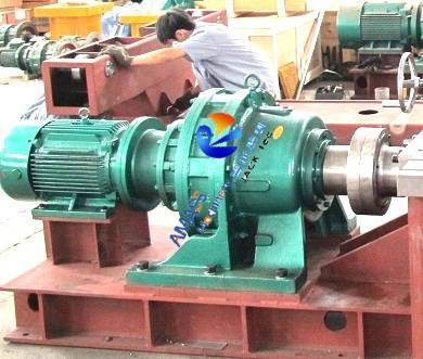
This is for driving revolving of the bottom straightening roller, so that the welding H Beam can be transported forward together with its straightening process, so that the entire length of the welding H Beam can be straightened in the machine;
6) Motor reducer: This is for driving rotation of the input and output conveyors of the H Beam Straightening Equipment;
7) Web clamp unit: (Fig.7)
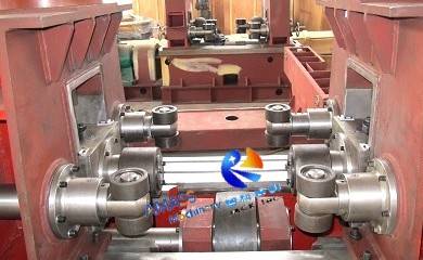
This unit includes two pairs of aligning rollers at front and back side of the main frame each. It for clamping web of H Beam during straightening period in the H Beam Straightening Machine;
8) Control board and Operation station: (Fig.8)
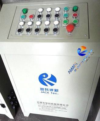
As a kind of automatic H Beam Production Machine, all the working actions of the YTJ series are manipulated with this operating station.
3. Technical Specification of YTJ-50 H Beam Flange Straightening Machine:
1) Main transmission system of the YTJ-50 (YTJ-40 also) models is adopted with 15KW motor and driven with gear speed reducer, of high transmission efficiency and rapid straightening speed (9m/min.);
2) Operation of the YTJ-50 high speed H Beam Straightening Machine:
a) Control board is put on the ground, away from the main frame;
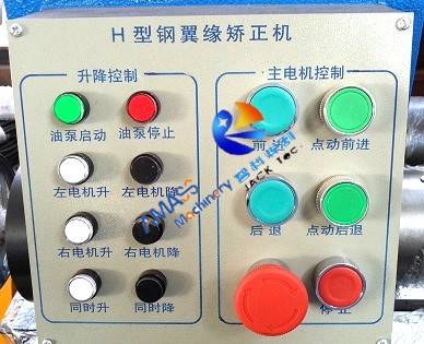
b) For convenient operation, operating panel is installed on the main frame close to the core T shape cavity straightening section;
c) Operating panel of YTJ40 and YTJ-50 models see below picture (Due to different straightening principle, operating panel of YTJ-60 and YTJ-80 Hydraulic I Beam Flange Straightening Machine is different from YTJ-40 and YTJ-50)
Operating panel: (Fig.9)
4. Technical Parameters of YTJ-50 Hydraulic H Beam Straightening Machine:
PARAMETER | Specification | NOTE |
Model | YTJ-50 Hydraulic I Beam Flange Straightening Machine |
Straightening Power | Hydraulic Pump station |
Suitable H Beam Material | Q345 | Tensile strength 510 ~ 600MPa |
Flange Thickness Range (s) (mm) | 6 ~ 50 | Special made available |
Flange Width Range (b) (mm) | 200 ~ 800 |
Web Thickness Range (a) (mm) | ≤40 |
Web Height Range (h) (mm) | 200-1500 |
H Beam Length Range (mm) | 4000 ~ 12000 |
|
Straighten Speed (mm/min) | ≈9000 |
|
Main Motor Power (kW) | 15 |
|
Hydraulic Station Power (kW) | 5.5 |
|
Power Supply | 3P 380V for China | Can be made on country of customer |


