A. Extensive Use and Operation of 180° Hydraulic Drive Steel Structure BOX H Beam Movable Turnover Machine:
1. Role of 180° Movable Flipping Machine for BOX H Beam Production:
1) 4 Times Welding Operation: In the process of BOX Beam and H Beam production, there are 4 pieces of welding seams in one piece of BOX H Beam, which will be fabricated with 4 sets of LHC model H Beam SAW Welding Machine respectively: One set of LHC completes one piece of welding seam;
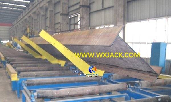
2) Transfer among LHC: At the completion of each time SAW welding, the workpiece BOX H Beam will be flipped 90° or 180°, and sent to next set of LHC. This task is fulfilled by means of 180° Movable Overturning Machine:
3) At Wuxi JACK automatic H Beam Production Line, large size welded H Beam being flipped and conveyed with 180° Movable Turnover Machine: (Fig.1)
2. Working Mode of 180° BOX H Beam Movable Overturning Machine:
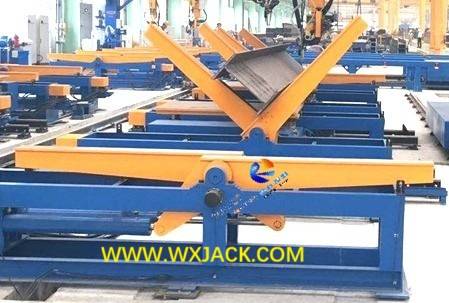
1) Manipulator Quantity: There are 2 pieces of L shape overturning rack in one set of 180° Movable Turnover Machine, for holding on long length of BOX Beam and H Beam, and used for 90° and 180° overturning at the completion of SAW welding operation:
2) Finished welded H Beam, being turned over with 180° Movable Turnover Machine in automatic H Beam Production Line: (Fig.2)
3. Work Zone of 180° BOX H Beam Movable Flipping Machine:
This equipment is placed at:
1) At SAW welding zone of automatic H Beam Production Line, between the 4 sets of LHC mode H Beam Submerged Arc Welding Machine, adjacent to 60° stationary turnover rack machine groups;
2) At H Beam Flange Straightening zone of automatic H Beam Production Line, alongside H Beam Flange Straightening Machine, for flipping H Beam 180° to the other side, for straightening on the other side of flange;
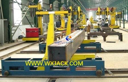
3) At SAW welding zone of automatic BOX Beam Production Line, between the 4 sets of column structure or moving gantry frame structure BOX Beam SAW Welding Machine:
4) 180° Steel Structure BOX H Beam Movable Turnover Machine holding on a piece of BOX Beam, at SAW machine of BOX Beam production line: (Fig.3)
4. Operating Mode of 180° BOX H Beam Movable Flipping Machine:
1) Hydraulic Drive: Driven with 2 pieces of hydraulic oil cylinders, 2 pieces of rockshafts revolve in phase simultaneously, overturning and carrying BOX H Beam onto conveyor rack of SAW welding machine;
2) Convey H Beam: By way of lifting moving machine, BOX Beam and H Beam is sent to next set of SAW welding machines;
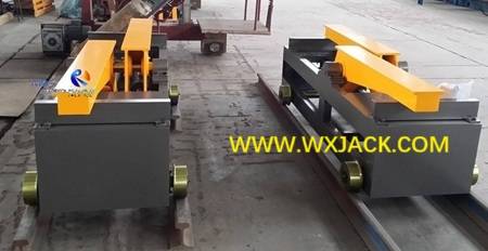
3) Movement of this 180° Movable Turnover Machine and workpiece BOX H Beam, is driven with motor reducer, and guided with moving wheels at the mechanical body. The movement is along parallel rails:
4) Parallel rails and wheels of 180° BOX H Beam Movable Flipping Machine at Wuxi JACK workshop: (Fig.4)
B. Technical View on and Advantages of 180° Hydraulic Drive Steel Structure BOX H Beam Movable Overturning Machine:
1. Main Units: This BOX H Beam Movable Turnover Machine is composed of mechanical main frame, hydraulic system and electrical system;
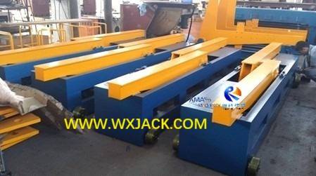
2. Mechanical main frame is composed of rockshaft (L arm, or rack, manipulator of the machine), BOX structure base bed, moving wheels, moving drive motor reducer:
Batch of 180° Movable Flipping Machine finished production, ready for shipment at Wuxi JACK workshop: (Fig.5)
3. Major Working Steps of 180° BOX H Beam Movable Overturning Machine:
1) During operation, workpiece BOX H Beam is raised off 60° racks of SAW welding Machine;
2) Then, driven with oil cylinder, rockshafts L shape racks of the machine overturn the workpiece BOX H Beam 90° or 180°;
3) After that, workpiece is moved BOX H Beam elevating moving machine, and be transported to next station of the next set of H Beam SAW Welding Machine, or H Beam Straightening Machine;
4. Strong Points of Operating Wuxi JACK 180° BOX H Beam Movable Turnover Machine:
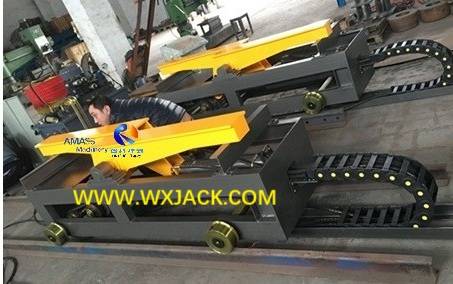
1) Cables and oil pipes of this machine are arranged through drag chain, applicable for complicated operation of workpiece rotation and convey. It has safe work, good appearance and reliable performance:
2) Cable routing with drag chain in the machine: (Fig.6)
3) The entire set of BOX H Beam Movable Turnover Machine is compact in structure and easy in operation, applicable for being applied in various automatic steel structure production line.
C. Range of Supply of the 180° Hydraulic Drive Steel Structure BOX H Beam Movable Flipping Machine:
One set of the equipment includes:
1. Two sets of motor reducer and mechanical frame each;
2. Four sets of workpiece BOX H Beam overturning drive oil cylinder, rockshaft (L shaped rack or arm), turnover bearing bed, moving wheels (with bearing and bearing bed), and oil pipe;
3. One set of 11kW hydraulic pump station;
4. One set of electrical control board and operating pendant/ panel.
D. Technical Parameters of 180° Hydraulic Drive Steel Structure BOX H Beam Movable Turnover Machine:
BOX H Beam Turning Angle Range of Movable Turnover Machine | 0° ~ 180° |
Workpiece BOX H Beam Weight | ≤20 Ton |
Moving Drive Motor Reducer Power | 1.5 kW |
Workpiece BOX H Beam Moving Speed | 5,000 mm/min. |
Max. Pressure of Hydraulic System | 16 MPa |
Center Distance of Moving Rail | 700mm (Distance upon workpiece L) |


