A. Application of 90° Steel Structure BOX H Beam Hydraulic Tipping Rack Machine:
1. Function: The 90° Tipping Rack Equipment has overturning range of 0 ~ 90° for steel structure members, especially H Beam/ T Beam/ BOX Beam;
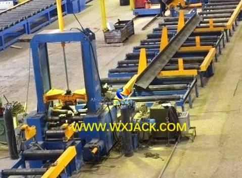
2. Where Used: In the process flow of automatic H Beam Production Line, the 90° Turnover Rack Equipment locates alongside output conveyor roller tables of H Beam Assembly and Tack Welding Machine. It is for flipping T Beam/ H Beam to the other side, so as to fitting up and have stitch welding on opposing side of T/ H Beam;
3. At Automatic H Beam Production Line: 90° Tipping Rack Machine turns over assembled H Beam on output conveyor of H Beam Assembly Machine: (Fig.1)
B. Working Steps of 90° Steel Structure BOX H Beam Hydraulic Tipping Rack Equipment:
Shown in below sketch, indicating on the above described T Beam and H Beam assembly and tack welding steps: (Fig.2)

In automatic H Beam Production Line:
1. First Step: this 90° Steel Structure H Beam Hydraulic Tipping Rack Machine flips the assembled and tack welded “┷” Beam clockwise or counterclockwise 90°;
2. Second Step: With the help of overhead traveling crane and its hoist hook, the 90° Steel Structure Hydraulic Turnover Rack Machine flips the “┣” Beam or “┫” Beam another 90° into “T” Beam;
3. Third Step: The “T” Beam is sent into input conveyor roller table of H Beam Assembly and Tack Welding Machine the 2nd time, for assembling T Beam into finished H Beam;
4. Fourth Step: The H Beam Assembly and Tack Welding Machine has assembly and tack welding on the 2nd piece of web onto the “T” Beam, fabricating the workpiece being assembled and spot welded into “工” Beam;
5. Fifth Step: The 90° Steel Structure Hydraulic Tipping Rack Equipment flips the “工” Beam clockwise or counterclockwise 90° into “H” Beam;
6. Sixth Step: The H Beam is sent to the next station of H Beam Production Line: LHC H Beam Submerged Arc Welding, by means of movable 180° Hydraulic Turnover Rack Equipment.
C. Structure, Working Principle and Operation of 90° Steel Structure BOX H Beam Hydraulic Turnover Rack Machine:
1. Main Units of 90° Steel Structure H Beam Hydraulic Tipping Rack Machine:
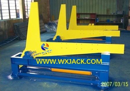
As can be checked from attached pictures, one set of the equipment is composes of:
1) Mechanical base bed, BOX structure, stationary, at the bottom of the machine, being fixed into workshop at customer workshop;
2) Overturning L arms, its rotation is driven with hydraulic cylinders. Being assembled onto the mechanical base bed;
3) Revolving transmission shaft, being assembled inside mechanical base bed;
4) Hydraulic oil cylinder, also being assembled inside mechanical base bed;
5) Hydraulic pump station, being put individually alongside the Hydraulic Tipping Rack Machine, being connected with oil cylinder by means of hoses;
6) Electric control board/ operating panels;
7) A set of assembled, tested, painted Wuxi JACK 90° H Beam Hydraulic Turnover Rack Equipment: (Fig.3)
2. Rotation of L arm is driven with hydraulic cylinder;
3. Ingenious Design on Wuxi JACK H Beam Hydraulic Tipping Rack Equipment:
1) Prevent from H Beam Falling Down: As shown in the photos, there is a small rack being fit on each of the L arm, of the 90° Steel Structure Turnover Rack Equipment. Its usage is to reliably hold the “┷” Beam onto the Turnover Rack, and preventing H Beam from unexpected falling down, during L shape Tipping Rack tilting procedure in the equipment:
2) Small protection brackets being assembled onto Tipping Rack of Wuxi JACK 90° Hydraulic Tipping Rack Equipment: (Fig.4)
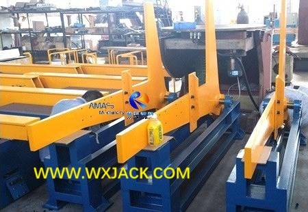
3) Flexible Position Change along Turnover Rack: As can be found from above photo, based on size of the “┷” Beam,there are three shifts of mounting positions for the small rack on the L arm Tipping Rack, in the form of 3 groups of holes.
D. Put into Use on 90° Steel Structure BOX H Beam Hydraulic Turnover Rack Equipment:
1. Installation: During installation of automatic H Beam Production Line, mechanical base of the Steel Structure H Beam 90° Hydraulic Turnover Rack Machine is fixed into workshop floor with anchor bolts;
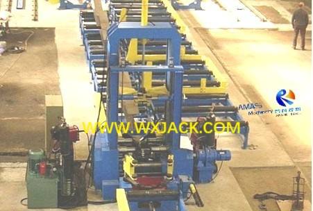
2. Application Form: Same as 60° Tipping Rack Machine, the 90° Turnover Rack Machine also works in 3 sets per group:
Vertical view on group of (3 sets in a group) 90° Hydraulic Turnover Rack Equipment, on output conveyor roller table of H Beam Assembly Machine: (Fig.5)
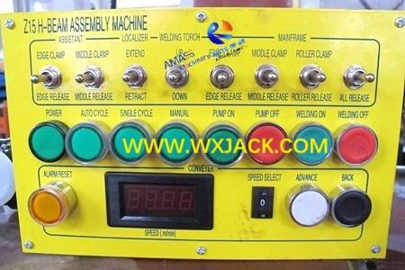
3. Operation Form: Under majority conditions, operating buttons of the H Beam 90° Hydraulic Turnover Rack Machine is integrated into operating panel of the H Beam Assembly and Tack Welding Machine. And it can also be made as an individual pendant, depending on practical customer requirement:
Operating panel of Wuxi JACK H Beam Assembly Machine: (Fig.6)
4. Other Application: Besides flipping the H Beam in automatic H Beam Production Line, this H Beam 90° Hydraulic Tipping Rack Machine can also be used in other application site, where 90° or minus overturning is necessary.
E. Technical Parameters of 90° Steel Structure BOX H Beam Hydraulic Tipping Rack Machine:
Flipping Angle of Steel Structure H Beam Turnover Rack Equipment | 0 ~ 90° |
Applicable H Beam Flange Width | 200~ 800 mm |
Applicable H Beam Web Height | 200~ 1500 mm |
Applicable Workpiece H Beam Weight | ≤20 Ton |
Max. Hydraulic Pressure | 14 MPa |


