A. Finished Steel Structure Parts of HB1800 Automatic Welded I H Beam Welding Production Line:
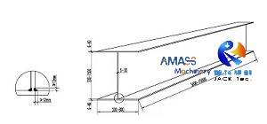
1. Output: The HB1800 I H Beam Production Machine tools group produces middle sized welded H Beam of up to 1800mm web height:
Design sketch on welded H Beam as finished workpieces: (Fig.1)
2. Process Technology:
In terms of H Beam production steps, HB1800 model line shares the same process technology with HB2000 and HB1500. The difference among the three models lies in:
1) The max. height of H Beam web (1500mm/ 1800mm/ 2000mm);
2) Models and specifications of H Beam Production Machine adopted in the line;
To be specific:
1) Z15/ Z18/ Z20 I H Beam Assembly Machine (1500mm/ 1800mm/ 2000mm);
2) LHA/ LHC/ LHT I H Beam SAW Welding Machine;
3) HYJ (Motor drive straightening)/ YTJ (Hydraulic oil cylinder drive straightening) I H Beam Straightening Machine.
B. Work Process of HB1800 (HB1500/ HB2000) Automatic Welded H Beam Production Machine Tool Group:
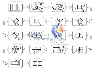
Please check the attached second illustration on illustration of process technology on automatic welded H Beam production: (Fig.2)
1. Raw Material Preparation:
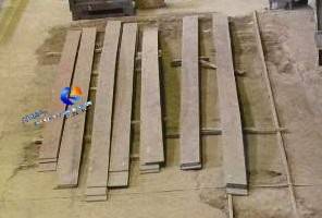
1) This is made with CG series CNC Strip plate cutting Machine: Carbon steel plate is cut into two pieces of flange and one piece of web:
2) Long and small width steel strips, as input of I H Beam Assembly Machine: (Fig.3)
2. H Beam Assembly and Tack Welding in I H Beam Assembly Machine:
This is implemented with the 1st set of critical I H Beam Production Machine for H Beam assembly:
1) Raw Material Input: One piece of flange and web each are hoisted onto input conveyor roller table of the Z18 I H Beam Assembly Machine;
2) The 1st Stage Assembly: The flange and web are clamped and positioned on input conveyor roller table of the machine;
3) Final and Precise Assembly: The flange and web are positioned and centered precisely (Assembling);
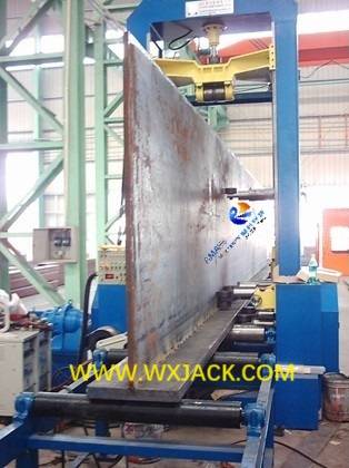
4) Assembly and Stitch Welding: The flange and web are spot welded automatically into ⊥ shape in the gantry frame of the machine: (Fig.4)
5) Half Completion: Hoist the semi-finished T Beam off output conveyor of I H Beam Assembly Machine, and flipped 180° to the opposing side;
6) The second piece of flange is hoisted onto input conveyor of the Z18 machine: (Fig.5)
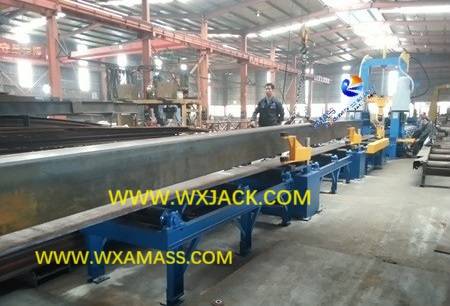
7) T Beam Assembly: The second time automatic assembly and spot welding is carried out to fit up and strengthen the workpiece into assembled H Beam;
3. Flip and Transport Workpiece in Automatic H Beam Welding Production Line:
The transportation/ overturning WIP (Work in process) H Beam among machines and equipment in the line, is fulfilled automatically, instead of human intervention:
1) The welded 工 orientated H Beam is overturned 90° into H orientated Beam, by means of hydraulic drive 90° overturning Rack: (Fig.6)
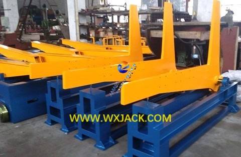
2) Transport H Beam onto travel cart of first welding area (With 2 sets of LHC model column trolley structure H Beam SAW Welding Machine) through conveyor;
3) Lifting unit of the travel cart raises the H Beam off the conveyor, and by means of the travel cart, the H Beam is sent onto overturning rack of 2 SAW Welding zones in the line;
4. The 1st Welding Zone: LHC Model H Beam SAW Welding Machine:
This is the 2nd type of critical equipment in H Beam Welding Production Line:
1) The overturning rack overturns H Beam, for carrying out 45° fillet welding;
2) The 1st set of H Beam SAW Welding Machine fulfils the first SAW welding seam on H Beam automatically: (Fig.7)
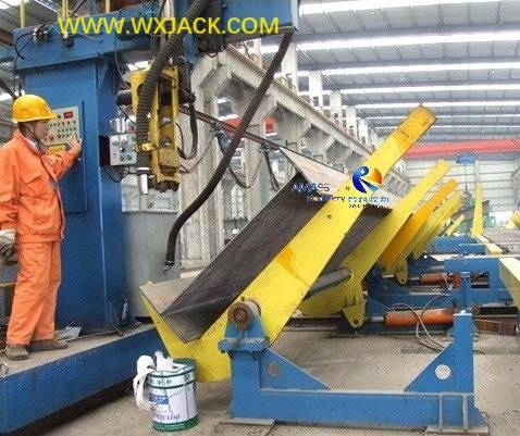
3) The 60° overturning rack overturns the H Beam 45° back to its original position;
4) The H Beam is sent onto overturning rack of the second set of LHC machine;
5) The H Beam is flipped another 45°, and completed welding the second piece of SAW seam on H Beam;
5. Flip and Transport WIP in Automatic Welded I H Beam Welding Production Line:
1) The H Beam is transported onto conveyor through hydraulic drive travel cart;
2) The H Beam is sent onto the movable 180° overturning rack of first welding area, by means of the conveyor: (Fig.8)
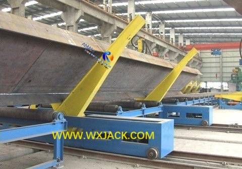
3) The H Beam is overturned 180° and sent to the second welding area by way of conveyor;
6. The 2nd Welding Area: LHC Model I H Beam SAW Welding Machine:
In this zone, the 3rd and 4th pieces of SAW welding seam on H Beam (The opposite side), is completed here;
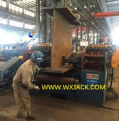
The welded H Beam is sent to HYJ series motor drive machine, for acquiring its flange deformation straightening: (Fig.9)
8. As Summary,
The entire working process of the automatic H Beam Welding Production Line features in:
High automation and fluent flow. Travel crane is seldom used;
Electric control system is reliable, and can have interlock among workstations.
This is the ideal automatic machine complex for H Beam production.
C. Technical Parameters of HB1800 Automatic Welded I H Beam Welding Production Line:
Model | HB1800 Automatic Welded I H Beam Production Machine Group |
Max. H Beam Web Width | 1800 mm |
H Beam Web Thickness | 6∽32 mm |
H Beam Flange Width | 200∽800 mm |
H Beam Flange Thickness | 6∽40 mm |
H Beam Length | 4000∽12000 mm |
Max. H Beam Weight | 20 Ton. |
Model of H Beam Assembly Machine | Z18 |
Model of H Beam SAW Welding Machine | LHC in automatic line |
Model of H Beam Straightening Machine | HYJ800 for light to medium duty; YTJ50/ 60/ 80 for heavy duty |
Transfer of H Beam workpiece among stations | Overturning Rack and Travel Cart |


